USA

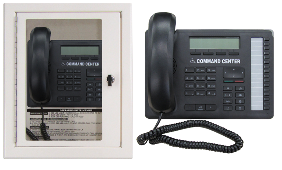
Command Center for 1-116 Elevator Phones
Only available in
COMPLIANT WITH

Overview
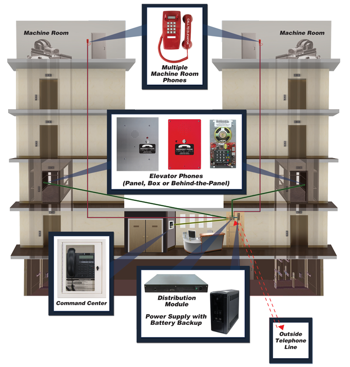
The Command Center System is designed to provide efficient two-way, person-to-person voice communication for elevators, accommodating an impressive range of 1 to 116 elevator phones.
- The system is compatible with most Rath and Janus Elevator phones, allowing the phone to be tailored to fit the specific needs of your elevator car
- Utilizing just one pair of wires between each elevator phone & Distribution Module, the system ensures easy and cost-effective installation
- All components are engineered to meet current industry codes, ensuring reliability and peace of mind
Power Requirements:
- Command Center and Sub-Master Stations are powered from the Distribution Module
Wiring Requirements:
- Command Center and Sub-Master to Distribution Module requires a single pair
- Machine Room Phone (2300-630RC) requires a single pair
- SmartPhones to Distribution Module requires a single pair
Phone Capabilities:
- Calls wait in queue until previous call is disconnected and receive a message stating that an emergency call is in progress. When the prior call clears, the next phone in queue is connected
- Includes handset and speaker phone for communication to phones
- Works with both Rath 2100 SmartPhones or Janus EMS phones
- LEDs indicate which phones have initiated a call
- Rescue personnel can communicate with individual phones and outside party
Distribution Module Features:
- Included with Command Center
- Install on a wall or table top
- Requires 120vac power with battery backup or Rath Power Supply with battery backup
- Single dedicated phone line or as an Intercom System
Additional Features:
- Standard system allows for a Command Center and a single Sub-Master Station (contact Rath for additional Sub-Masters)
- Audible alert sounds when phones place a call until Command Center or Sub-Master Station joins conversation
- Can be configured with the main Command Center and multiple Sub-Master Stations (available in desk, surface, or flush mount) and Command Center MachineRoom Phone 2300-630RC (which allows for additional onsite communication with all devices connected to the system)
Warranty: 2 years
Choose from Surface, Flush or Desk Mount
Available in 12, 16, 28, 36, 56, 76, 96, or 116 Zone
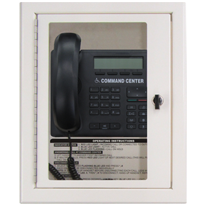 2500-__RC Series Surface Mount 2500-__RCF Flush Mount Surface Mount Zone: 12 (2500-12RC) 16 (-16RC) 28 (-28RC) 36 (-36RC) 56 (-56XRC) 76 (-76XRC) 96 (-96XRC) 116 (-116XRC) 2500-12RC, 16RC = 15.14″ H x 12″ W x 6.19″ D 2500-28RC, 36RC, 56XRC, 76XRC, 96XRC, 116XRC = 21.03″ H x 20.3″ W x 5.19″ D Flush Mount Zone: 12 (2500-12RCF) 16 (-16RCF) 28 (-28RCF) 36 (-36RCF) 56 (-56XRCF) 76 (-76XRCF) 96 (-96XRCF) 116 (-116XRCF) 2500-12RCF, 16RCF Front Frame: 16.06″ H x 14″ W x 3.07″ D Back Box: 15.64″ H x 12″ W x 3″ D 2500-28RCF, 36RCF, 56XRCF, 76XRCF, 96XRCF, 116XRCF Front Frame: 21.13″ H x 25″ W x 3.06″ D Back Box: 20.66″ H x 23″ W x 3″ D | 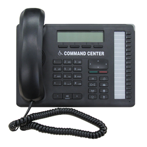 2500-__NC Series Desk Mount See data sheet for dimensions Zone: 12 (2500-12NC) 16 (-16NC) 28 (-28NC) 36 (-36NC) 56 (-56XNC) 76 (-76XNC) 96 (-96XNC) 116 (-116XNC) |  Distribution Modules 12-36 Zone System = 2.04″ H x 17.28″ W x 11.8″ D 56-116 Zone System = 6.83″ H x 17.18″ W x 8.9″ D |
Files and Resources
2500 Series_Command Center Data Sheet
Datasheets
2500 Series_Sub-Master Station Data Sheet
Datasheets
2300-630RC_Command Center Machine Room Phone Data Sheet
Datasheets
Command Center Block Wiring Diagram
Installation, programming and wiring
Command Center Engineering Specifications
Specifications
Command Center System Riser Diagram With Multiple Machine Rooms Data Sheet
Datasheets
Command Center Typical System Layout Wiring Diagram
Installation, programming and wiring
Command Center Typical System Layout with Cellular Wiring Diagram
Installation, programming and wiring
Command System Supervision (with Cellular) Wiring Diagram
Installation, programming and wiring
Command System Supervision Data Sheet
Datasheets
Command System Supervision Data Sheet
Datasheets

Specifiers’ Corner
The Specifiers’ Corner is designed to provide Architects, Engineers, Contractors, Fire Marshals, Building Code Officials, Inspectors, AHJs, and end users with the essential information that may be needed for a project: Submittal Documents, Manuals/Wiring Diagrams, Data Sheets,CAD and Code Requirements
Contact info
You also can contact us through our phone number, our email address, and we’ll get back to you


Education, Training and Support

We believe that ongoing education is paramount to your professional development.
As the code and training experts, our website offers all the documentation and educational resources needed to assist you in making the right decisions.